 Gusset Plate Settings
- General Overview
- Tips and Tricks
- Related Tools
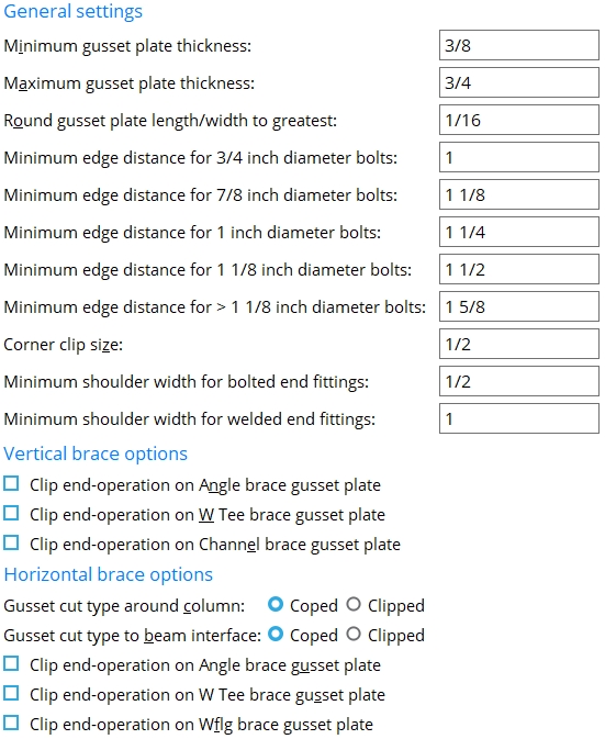
General settings
Minimum gusset plate thickness: The minimum gusset plate thickness to be applied to system connection gusset plates on horizontal and vertical braces.
Maximum gusset plate thickness: The maximum gusset plate thickness to be applied to system connection gusset plates on horizontal and vertical braces.
Round gusset plate length/width to greatest: The distance by which you want connection design to increment the length and width of gusset plates (e.g., 1/2 makes connection design round up to the nearest half inch).
| 3/4 inch (20 mm) diameter bolts: | The distance from the edge of the gusset plate to the center of the nearest hole. The "NM bolt diameter" (horizontal brace) or "NM bolt diameter" (vertical brace) sets the bolt diameter. |
| 7/8 inch (22 mm) diameter bolts: | |
| 1 inch (24 mm) diameter bolts: | |
| 1 1/8 inch (27 mm) diameter bolts: | |
| > 1 1/8 inch (27 mm) diameter bolts: |
|
ed = edge distance for bolting the interior of the gusset plate to the brace. A vertical brace is shown. The |
|
ed = edge distance for the framing edge of a gusset when the gusset fastens to the supporting member with a clip angle. A vertical brace is shown. The " Minimum edge distance for xx diameter bolts " entered here also applies to horizontal braces. |
Corner clip size: A distance. SDS2 connection design applies the value that is entered here as the " Corner clip " in the " ![]() Gusset Column Cap " leaf when " Corner clip " is unlocked (
Gusset Column Cap " leaf when " Corner clip " is unlocked ( ![]() ). " Corner clip " is unlocked by default.
). " Corner clip " is unlocked by default.
|
A corner clip is a 45 degree clip cut to the gusset plate at the corner where the gusset plate, column plate and column meet. A " Corner clip " of ' 0 ' makes the corner square (not cut).The corner clip distance is measured perpendicular to or parallel with the work line of the supporting column, from one corner of the clip cut to the other. |
| Connection Design Locks | ||
| Brace Material (connection) |
Leaf Name | Lock |
| angle, tee, channel | Gusset Column Cap | Corner clip |
| stem-vertical tee | Gusset Column Cap | Corner clip |
|
web-vertical wide flange
(standard) |
Gusset Column Cap | Corner clip |
|
web-vertical wide flange
(paddle plates) |
Gusset Column Cap | Corner clip |
|
web-horizontal wide flange
(claw angles) |
Gusset Column Cap | Corner clip |
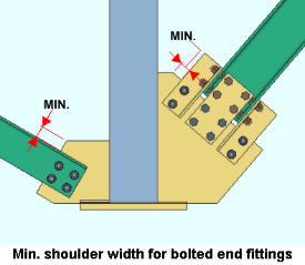
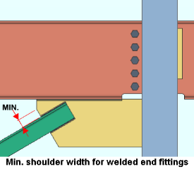
Minimum shoulder width for bolted and welded end fittings: A distance that sets the minimum dimension from the edge of brace, or additional brace connection material if required, to the shoulder of the gusset. Bolted connections use the "bolted end fittings " setup field in the Gusset Plate Settings window, whereas welded connections use the " welded end fittings " setup field to determine minimum shoulder width.
Vertical brace options
Clip end operation on angle brace gusset plates: ![]() or
or ![]() . This applies when " Clip end operation " is set to ' Automatic ' under "
. This applies when " Clip end operation " is set to ' Automatic ' under "![]() Connection specifications" on the Vertical Brace Edit window. It applies to a vertical brace whose " Section size " is an angle (L). The option applies to most vertical brace framing situations , but not to an intersection plate or a brace that is perpendicular to the supporting member. If the connection is for a " Seismic brace ," the gusset plate will always be clipped, regardless of the choice made here or to " Clip end operation " on the Vertical Brace Edit window..
Connection specifications" on the Vertical Brace Edit window. It applies to a vertical brace whose " Section size " is an angle (L). The option applies to most vertical brace framing situations , but not to an intersection plate or a brace that is perpendicular to the supporting member. If the connection is for a " Seismic brace ," the gusset plate will always be clipped, regardless of the choice made here or to " Clip end operation " on the Vertical Brace Edit window..
|
||||||||||||||||||||||||||||
If this box is checked (
), connection design performs a ' Clip ' operation on the gusset plate to create an edge perpendicular to the vertical brace. This may not work if the angle (number of degrees) to the supporting beam or column is too small.
If the box is not checked (
), connection design does not perform the ' Clip ' operation, and the gusset comes to a point over the vertical brace.
Clip end operation on W tee brace gusset plates: ![]() or
or ![]() . This applies when " Clip end operation " is set to ' Automatic ' under "
. This applies when " Clip end operation " is set to ' Automatic ' under " ![]() Connection specifications " on the Vertical Brace Edit window. The option applies to vertical braces whose " Section size " is a W tee (WT) and whose "Stem orientation" is ' Horizontal '. The option applies to most vertical brace framing situations , but not to an intersection plate or a brace that is perpendicular to the supporting member.
Connection specifications " on the Vertical Brace Edit window. The option applies to vertical braces whose " Section size " is a W tee (WT) and whose "Stem orientation" is ' Horizontal '. The option applies to most vertical brace framing situations , but not to an intersection plate or a brace that is perpendicular to the supporting member.
|
||||||||||||||||||||||||||||
If this box is checked (
If the box is not checked (
Clip end operation on channel brace gusset plates: ![]() or
or ![]() . This applies when " Clip end operation " is set to ' Automatic ' under "
. This applies when " Clip end operation " is set to ' Automatic ' under " ![]() Connection specifications " on the Vertical Brace Edit window. The option applies to vertical braces whose " Section size " is a channel (C or MC). It applies to most vertical brace framing situations , but not to an intersection plate or a brace that is perpendicular to the supporting member.
Connection specifications " on the Vertical Brace Edit window. The option applies to vertical braces whose " Section size " is a channel (C or MC). It applies to most vertical brace framing situations , but not to an intersection plate or a brace that is perpendicular to the supporting member.
|
||||||||||||||||||||||||||||
If this box is checked (
If the box is not checked (
Horizontal brace options
Gusset cut type around column: Coped or Clipped . This applies when ' Automatic ' is selected for " Gusset cut " under " ![]() Connection specifications " on the Horizontal Brace Edit window. The option applies when a horizontal brace connects to the top flanges (shown) or webs (not shown) of two beams with an interposed column.
Connection specifications " on the Horizontal Brace Edit window. The option applies when a horizontal brace connects to the top flanges (shown) or webs (not shown) of two beams with an interposed column.
|
|
' Coped ' specifies that connection design make two cuts to the gusset plate so that it clears the interposed column.
' Clipped ' instructs connection design to make a single diagonal cut on the gusset plate so that it clears the interposed column. As can be seen in the illustration above, a larger gusset plate is likely to be designed when the ' Clipped ' option is selected.
Gusset cut type to beam interface: Coped or Clipped . This applies when ' Automatic ' is selected for " Gusset cut " under " ![]() Connection specifications " on the Horizontal Brace Edit window. The option applies when a horizontal brace connects to the top flanges (shown) or webs (not shown) of two beams.
Connection specifications " on the Horizontal Brace Edit window. The option applies when a horizontal brace connects to the top flanges (shown) or webs (not shown) of two beams.
|
|
' Coped ' specifies that connection design make two cuts to the gusset plate.
' Clipped ' instructs connection design to make a single diagonal cut on the gusset plate.
Clip end operation on angle brace gusset plates: ![]() or
or ![]() . This applies when " Clip end operation " is set to ' Automatic ' under "
. This applies when " Clip end operation " is set to ' Automatic ' under " ![]() Connection specifications " on the Horizontal Brace Edit window. The brace's " Section size " must be an angle (L). The option applies to most horizontal brace framing situations , but not to an intersection plate or a horizontal brace perpendicular to a beam
Connection specifications " on the Horizontal Brace Edit window. The brace's " Section size " must be an angle (L). The option applies to most horizontal brace framing situations , but not to an intersection plate or a horizontal brace perpendicular to a beam
|
|||||||||||||||||||||||||||||||||||||||||||||||||
If this box is checked (
If the box is not checked (
Clip end operation on W tee brace gusset plates: ![]() or
or ![]() . This applies when " Clip end operation " is set to ' Automatic ' under "
. This applies when " Clip end operation " is set to ' Automatic ' under " ![]() Connection specifications " for a horizontal brace whose " Section size " is a W tee (WT). The option applies to most horizontal brace framing situations , but not to an intersection plate or a horizontal brace perpendicular to a beam.
Connection specifications " for a horizontal brace whose " Section size " is a W tee (WT). The option applies to most horizontal brace framing situations , but not to an intersection plate or a horizontal brace perpendicular to a beam.
|
||||||||||||||||||||||||||||
If this box is checked (
If the box is not checked (
Clip end operation on Wflg brace gusset plate: This applies when " Clip end operation " is set to ' Automatic ' under " ![]() Connection specifications " for a horizontal brace whose " Section size " is a wide flange (W). The option applies to most horizontal brace framing situations , but not to an intersection plate or a horizontal brace perpendicular to a beam.
Connection specifications " for a horizontal brace whose " Section size " is a wide flange (W). The option applies to most horizontal brace framing situations , but not to an intersection plate or a horizontal brace perpendicular to a beam.
|
||||||||||||||||||||||||||||
If this box is checked (
If the box is not checked (


|
|
OK (or the Enter key) closes this screen and applies the settings.
Cancel (or the Esc key) closes this screen without saving any changes.
Reset undoes all changes made to this screen since you first opened it. The screen remains open.
- Horizontal brace (index)
- 'Hbrc plate' connections (help page)
- Horizontal brace connections (Connection Guide)
- Setup of horizontal braces (index)
- Vertical brace (index)
- Connection guide (examples of vertical brace connections)

